
USER MANUAL
Precautions
Acclimatization
If the box contents feel colder than room temperature then please wait 12 to 24 hours before proceeding with the installation. This allows potential condensation to evaporate, which could otherwise cause damage to your SIDFX, SID chips or computer during or after power-on.
Electro-Static Discharge (ESD) prevention
Precautions must be observed for handling electrostatic sensitive devices. Ideally both you and your computer should be properly grounded during installation in order to efficiently protect your SIDFX, SID chips and computer against electrostatic discharges.
Unfortunately this is not easily accomplished by most end users, but using an ESD wrist-strap is highly recommended.


With ESD wrist-strap
With ESD wrist-strap
ESD wrist-straps with integrated discharge resistor and grounding wire with alligator clip are available from e.g. eBay for as little as 1 USD.
First completely discharge yourself to a grounded metal part of your home (heating radiator, water pipe, kitchen sink, exposed metal on kitchen appliances etc.).
Then put on the wrist-strap and connect the alligator clip to the exposed metal cage that surrounds your computer’s expansion port connector, but be sure not to touch any of the connector contacts.
This will effectively put you and your computer at the same potential.

Without ESD wrist-strap
Using an ESD wrist-strap is highly recommended. But if you don’t have an ESD wrist-strap available then first completely discharge yourself to a grounded metal part of your home (heating radiator, water pipe, kitchen sink, exposed metal on kitchen appliances etc.).
Then touch the expansion port metal cage with your fingers before and regularly during installation.
This will help keeping the potential difference low.
Without ESD wrist-strap
Keep original packaging
We recommend that you keep the original packaging for SIDFX and any included accessories.

ESD protective packaging
As a minimum you should keep the ESD protective packaging included with SIDFX, i.e. the pink foam pad and the shielding bag.
These items are important in the event that you at some point in time need to uninstall SIDFX from your system.
Together they protect SIDFX against ESD events during storage and handling in addition to protecting the pins against bending or breaking.
ESD protective packaging included with SIDFX
Installation
Hand hygene recommendations
The original Commodore motherboard, chips and other internal parts may include lead and other toxic materials which were not regulated by law until years later. Therefore you should wash you hands and wipe off any used tools after finishing the installation. It is also recommended to wash your hands before installation. Good hand hygene also reduces transfer of dirt and natural oils onto parts and components during installation, which may otherwise cause long-term surface corrosion.
Opening computer
To avoid any risk of electric shock, make sure to turn off your computer and unplug all cables!
There are several online guides on how to open the computer, so please Google how to open a C64. Once inside you might need to remove a metalized cardboard cover or rigid metal shield that was used in some computer models.

Extract SID chip from its socket
The SID chip is typically marked MOS 6581, MOS 8580, CSG 6582 (same as 8580) or similar. Before removing your SID chip from the motherboard it is important to take note of its orientation. The orientation is utmost important in order to install SIDFX correctly.

Locate the notch
The notch indicates the location of the SID's pin 1. The SID socket and SIDFX have a similar notch and these must always match up!
Locate the SID chip notch

Safely extract the SID chip from its socket
Safely extract the SID chip
Use a wide flat-head screwdriver and carefully squeeze it in between the SID chip and its socket. Support the SID with a finger at each end while you gently twist the screwdriver from side to side in order to lift the SID chip a bit. Do the same from the other end and repeat until the SID chip is out.
Only twist the screwdriver, don't bend it upwards, otherwise you may cause damage to the pins.
NEVER EXTRACT CHIPS WITH YOUR FINGERS ONLY!
The goal is to keep the SID pins straight by keeping the chip as horizontal as possible during extraction, so keep switching ends and only slightly lift the chip by twisting the screwdriver until the SID releases itself from the socket.
Install SID chips into the SIDFX sockets
Now it's time to insert the SID chips you wish to use with SIDFX.
SIDFX relies on a SID chip installed in socket 1 so if you only have one SID then always install it in socket 1. SID 1 is the default SID in some operation modes (refer to operating modes below for more details).
If you plan on playing or composing stereo tunes using 6581+8580
then please install 6581 as SID 1 in order to allow standardizing.

Gently install your SID chips
Make sure that the notch of the SID chip and the notch of the SIDFX socket match up. Also make sure that all the SID chip pins are caught by the socket receptacles before applying any pressure to the SID chip.
A good method of inserting the SID chip is to support the SIDFX module with your index fingers while gently pressing down the SID chip with your thumbs until the SID is fully seated.
Avoid installing the SID chips while SIDFX is installed your computer because this may cause excess stress to the SIDFX module and the module pins.
Gently install SID chips into the SIDFX sockets
Provide clearance for SIDFX
SIDFX comes with a “riser socket” (extra IC socket) pre-installed on the SIDFX pins. This lifts SIDFX by additional 4 mm and allows clearing some of the components surrounding the SID socket. It also protects the SIDFX pins against accidental bending/breaking, so it’s recommended to keep the riser socket installed whenever possible.
However in some cases there may not be sufficient headroom, so the riser socket needs to be removed before installation. This is always the case when SIDFX needs to fit computers with a rigid metal shield covering the motherboard. Also see the platform specific instructions further below for information on which require removal of the riser socket.
Removal of the riser socket is performed with a wide screwdriver squeezed in between the riser socket and the fixed pin header of SIDFX, please also see the SID chip removal instructions above for the best approach.

Avoid short-circuits
Some computer models have tall components surrounding the SID socket, which may cause installation issues and/or short-circuits if not properly handled.
Therefore certain surrounding components must be slightly bent down in order to provide sufficient clearance for the SIDFX module.
Surrounding components prior to bending

Gently bend down tall components
Decide which direction would best fit your computer model and then slowly and gently push in that direction. Don't flip them back and forth, only one direction.
Some cylindrical components (electrolytic capacitors) cannot/must not be bent as this may damage them.
After bending make sure that there are no short-circuits between any of the component pins.
Surrounding components after bending
Platform specific instructions
In this section you will find instructions for your specific computer model. Some Commodore models were sold with a range of different motherboard revisions. Each revision has an ASSY number marked on the motherboard.
Locate your motherboard model for information regarding use of riser socket and placement of SID socket, MPU and expansion port.
Commodore 64 (bread-bin chassis)

ASSY 326298 - Riser socket required

ASSY 250425 - Riser socket required

ASSY 250407 - Riser socket required

ASSY 250469 - Riser socket recommended
Commodore 64C (slim chassis)

ASSY 250466 - Riser socket must be removed
ASSY 250469 - Riser socket must be removed
Commodore 128 (slim chassis) / Commodore 128D (plastic desktop chassis)

ASSY 310379 - Riser socket must be removed
Commodore 128DCR (metal desktop chassis)

Unscrew the power supply held by 4 screws and move it to the side (note the orientation of the power connector going to the motherboard)
Install SIDFX and the grabber cables (use the riser socket), see the Install SIDFX module and Install SIDFX cables sections below for further information.

Unscrew the supporting standoff and replace it with a screw from another location, where you screw in the removed standoff for safe keeping

Re-install the power supply but use the side screw to lift the power supply above its original position (remember to re-install the power connector). On the opposite side install the provided self-adhesive rubber bumper underneath the power supply so it is supported by the VIC/VDC metal cage.
Commodore SX-64 (portable computer chassis)

Locate and gain access to the CPU board
Gently bend down all the components surrounding the SID socket but avoid causing short-circuits between them.
Install SIDFX and the grabber cables (use the riser socket), see the Install SIDFX module and Install SIDFX cables sections below for further information.
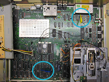
Connect the blue and green grabbers to the standard MPU locations but connect the yellow grabber to UC1 pin 10 (marked 74LS139 or similar).
ASSY 251102 - Riser socket required
C64 Reloaded MK1 (by Individual Computers GmbH)
If you use C64 Reloaded with a C64C chassis then our SIDFX adapter for C64 Reloaded MK1 is required in order to fit SIDFX below the keyboard. The adapter is included with the SIDFX bundle for C64 Reloaded MK1 and available separately as an accessory.

Prepare SIDFX and the C64 Reloaded adapter
The riser socket from SIDFX must be moved to the pins of the adapter in order to lift it. Removal is performed with a wide screwdriver squeezed in between the riser socket and the fixed pin header of SIDFX, please also see the SID chip removal instructions above for the best approach.
Make sure the notches on SIDFX, the adapter and the riser socket match up!
Install the provided self-adhesive rubber bumper on the round component marked “151” in the center of the SIDFX module. This will ensure clearance between SIDFX and the motherboard.
Move riser socket to adapter and install bumper

Prepare the C64 Reloaded motherboard
C64 Reloaded must be jumped for “6581” operation before installing SIDFX. Please refer to the C64 Reloaded manual for specific instructions.
C64 Reloaded must be jumped to “6581” operation
C64 Reloaded MK2 (by Individual Computers GmbH)
Our SIDFX adapter for C64 Reloaded MK2 is required in order to allow the motherboard to detect SIDFX as an 6581 SID and provide 12V to the SID 1 socket of the motherboard. Otherwise the motherboard is unable to supply sufficient power to SIDFX. The adapter is included with the SIDFX bundle for C64 Reloaded MK2 and available separately as an accessory.
Prepare SIDFX and the C64 Reloaded adapter
The riser socket from SIDFX must be moved to the pins of the adapter in order to lift it. Removal is performed with a wide screwdriver squeezed in between the riser socket and the fixed pin header of SIDFX, please also see the SID chip removal instructions above for the best approach.
Make sure the notches on SIDFX, the adapter and the riser socket match up!
Install the provided self-adhesive rubber bumper on the round component marked “151” in the center of the SIDFX module. This will ensure clearance between SIDFX and the motherboard.
Move riser socket to adapter and install bumper

Prepare the C64 Reloaded motherboard
C64 Reloaded must be configured to the default SID settings "Mono SID 1". This is done using the "Audio output" and "Stereo SID options" menus accessible through the USB serial console. Please refer to the C64 Reloaded manual for specific instructions.
The Reloaded SID 2 socket must be left unused while SIDFX is installed!
After installation you must verify that SIDFX (SID 1) is correctly detected as an 6581 SID chip. This is done through the "Chipset info" menu accessible through the USB serial console. Please refer to the C64 Reloaded manual for specific instructions.
C64 Reloaded must be configured to“Mono SID 1”
Install SIDFX module
Now it's time to install SIDFX into the SID socket of the motherboard.

Gently install the SIDFX module
Make sure that the notch of the SIDFX module's board-to-board connector and the notch of the motherboard SID socket match up. Also make sure that all the SIDFX pins are caught by the motherboard socket receptacles before applying any pressure to the SIDFX module.
A good method of installing SIDFX is to gently press down the module in the top and bottom center region using your thumb and index fingers.
Avoid installing SIDFX by pressing down on the SID chips because this may cause excess stress to the SIDFX module.
Gently insert SIDFX into the motherboard socket
Install SIDFX cables
What is the purpose of the 4 provided cables?
-
OUT: The stereo audio cable allows connecting e.g. head-phones, external speakers or recording equipment. The left and right audio channels are a direct result of the active SIDFX configuration (refer to operating modes below for more details) and the position of switch 1, which will override the audio path when not in the center position (see SW1 below for more details). The C64 mono output (available at the A/V connector) is always a mix of the left and right audio channels.
-
SW1: Switch 1 allows manual SID selection. In the center position the audio output is controlled by the active configuration or API (refer to operating modes below for more details). With the factory default settings this effectively means SID 1 in the left audio channel and SID 2 in the right audio channel (if two SIDs are installed). In the left position the audio output from SID 1 will be routed to both output channels. In the right position the audio output from SID 2 will be routed to both output channels.
-
SW2: Switch 2 allows choosing between user-configurable profiles (also required for installing firmware updates). It is polled at every power-on and reset and provide up to 3 profiles (center/left/right). This allows you to quickly choose a specific SIDFX operating mode before loading a program, e.g. a demo or music editor (refer to operating modes below for more details).
-
BUS: The mini-grabber cable allows mapping SID 2 to an alternate address space. The 3 grabbers capture the address lines required in order to allow enabling stereo SID playback (refer to operating modes below for more details).

Permanently install the cables
The use of each individual cable is optional but if you chose not to install one or more cables then the corresponding feature(s) will be unavailable. All cables are required in order to take advantage of all SIDFX features.
When installing the cables please observe the connector function printed next to each connector (OUT/SW1/SW2/BUS). The switches and audio output connector should be installed permanently by e.g. drilling a hole in a suitable location and screwing it in place. Consider locations where the chassis wall is thin enough to allow mounting the nut on the threading.
A switch may short-circuit your computer if left rattling around inside or outside the chassis!
The key/tab on the switch marks the LEFT position

MPU grabber locations
The blue and green grabbers must be connected to the MPU.
The MPU chip is typically marked MOS 6510 (old C64), MOS 8500 (new C64), MOS 8502 (C128) or similar.
Connect the blue grabber to the A5 signal at MPU pin 12.
Connect the green grabber to the A8 signal at MPU pin 15.
Grabbers connected to MPU pins 12 and 15

Expansion port grabber location
The yellow grabber must be connected to the expansion port (except for SX-64, see platform specific instructions).
Connect the yellow grabber to the IO1 signal at expansion port pin 7.
Grabber connected to expansion port pin 7
Re-install shielding
Now it's time to re-install the original shielding. This section is only applicable to models with rigid metal shielding.

Clean the SID cooling finger and bend it upwards
Shielding considerations
First clean the “cooling finger” that previously touched the SID chip, then bend it upwards so it won’t touch any of the SIDFX components (not doing so may short-circuit and destroy the SIDFX unit).
It may be increasingly difficult to re-install the shielding while the grabbers are in place. On some motherboard revisions there are alternate locations to tap off the A5 and A8 signals that might allow easier re-fitting of the metal shielding (please contact us for further details).
In some cases the shield cannot be screwed fully down in all locations. In rare cases the metal shielding may need to be slightly modified in order to be re-installed.
Hand hygene recommendations
The original Commodore motherboard, chips and other internal parts may include lead and other toxic materials which were not regulated by law until years later. Therefore you should wash you hands and wipe off any used tools after finishing the installation.
Post-installation testing
After finishing the hardware installation please verify your setup by using the diagnostics features of our SIDFX configuration tool which is available on our download page.
Use configuration tool to verify hardware installation
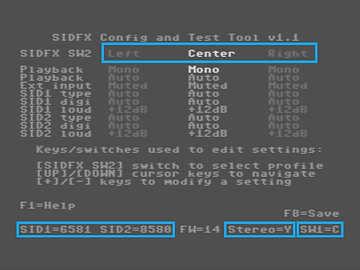
SIDFX configuration tool
Verify that your SIDs are correctly detected (see the bottom status line). The SID chips should always be detected as either 6581, 8580 or NONE (if no SID is installed). SIDs detected as unknown (UNKN) are operated in "safe mode" at 9V and with 8580 filter capacitors so the SID will not be damaged, but may not operate properly for several reasons. Please visit our support page in case you experience that SIDs are being incorrectly detected.
Also verify the function and orientation of the two switches. The bottom status line shows you the position of switch 1. Switch 2's position is indicated by the configuration column on the screen that is highlighted.
The bottom status line also shows whether your SIDFX is stereo capable or not “Stereo=Y” for yes or “Stereo=N” for no. For stereo capability two SIDs must be (correctly) detected and all 3 grabber cables must be installed in the correct locations.
Configuration
Custom configurations
The SIDFX configuration tool is used to manage 3 custom configuration profiles which allows you to quickly set a specific SIDFX operating mode before loading a program, e.g. a demo or music editor (refer to operating modes below for more details).
Switch 2 controls which configuration profile is loaded at the time of reset or power-on. With the switch positions CENTER, LEFT and RIGHT you have 3 user configurable profiles. When you change and save a configuration profile using the configuration tool it will be safely stored to a flash memory within the SIDFX unit.
Operating modes
Operating modes are used to alter the behavior of SIDFX to match different use cases. Operating modes can be selected through the SIDFX configuration tool or through the SIDFX API.
Switch 1 controls the audio output routing. In the CENTER switch position the audio output is controlled by the active SIDFX configuration. With the factory default settings this effectively means SID1 in the left audio channel and SID2 in the right audio channel (with two SIDs installed). In the LEFT switch position the audio output from SID1 will be routed to both output channels. In the RIGHT switch position the audio output from SID2 will be routed to both output channels.
Mono: Auto
This is the factory default.
When two SIDs are installed SIDFX operates in "Mono; SID1+SID2" mode, otherwise in "Mono; SID1 only" mode.
Mono: SID1 only
SID1 and SID2 are both located at $D400. SID register writes go to both SIDs, so they always play the same. For early SIDFX units SID register reads always come from SID1. On newer SIDFX units SID register reads come from SID2 when SID2 is forced using switch 1, otherwise from SID1. Please visit our support page for more information on this topic.
Both audio channels come from SID1 provided that switch 1 is in the CENTER position. Switch 1 can be used to force the audio output to come from SID1 (LEFT position) or SID2 (RIGHT position).
Note: POTX/POTY register reads always come from SID1 (where these signals are electrically connected) in order to not disturb e.g. paddle operations.
Mono: SID2 only
SID1 and SID2 are both located at $D400. SID register writes go to both SIDs, so they always play the same. For early SIDFX units SID register reads always come from SID2. On newer SIDFX units SID register reads come from SID1 when SID1 is forced using switch 1, otherwise from SID2. Please visit our support page for more information on this topic.
Both audio channels come from SID2 provided that switch 1 is in the CENTER position. Switch 1 can be used to force the audio output to come from SID1 (LEFT position) or SID2 (RIGHT position).
Note: POTX/POTY register reads always come from SID1 (where these signals are electrically connected) in order to not disturb e.g. paddle operations.
Mono: SID1+SID2
SID1 and SID2 are both located at $D400. SID register writes go to both SIDs, so they always play the same. For early SIDFX units SID register reads always come from SID1. On newer SIDFX units SID register reads come from SID2 when SID2 is forced using switch 1, otherwise from SID1. Please visit our support page for more information on this topic.
The left audio channel comes from SID1 and the right audio channel comes from SID2 provided that switch 1 is in the CENTER position. Switch 1 can be used to force the audio output to come from SID1 (LEFT position) or SID2 (RIGHT position).
Note: POTX/POTY register reads always come from SID1 (where these signals are electrically connected) in order to not disturb e.g. paddle operations.
Stereo: SID2 at $D420
SID1 is located at $D400 and SID2 at $D420. SID register writes go to the individual SID being addressed and SID register reads come from the individual SID being addressed.
The left audio channel comes from SID1 and the right audio channel comes from SID2 provided that switch 1 is in the CENTER position. Switch 1 can be used to force the audio output to come from SID1 (LEFT position) or SID2 (RIGHT position).
Note: POTX/POTY register reads come from the individual SID being addressed. The POTX/POTY pins of SID2 are not connected and will thus return 0x00.
Stereo: SID2 at $D500
SID1 is located at $D400 and SID2 at $D500. SID register writes go to the individual SID being addressed and SID register reads come from the individual SID being addressed.
The left audio channel comes from SID1 and the right audio channel comes from SID2 provided that switch 1 is in the CENTER position. Switch 1 can be used to force the audio output to come from SID1 (LEFT position) or SID2 (RIGHT position).
Note: POTX/POTY register reads come from the individual SID being addressed. The POTX/POTY pins of SID2 are not connected and will thus return 0x00.
Stereo: SID2 at $DE00
SID1 is located at $D400 and SID2 at $DE00. SID register writes go to the individual SID being addressed, and SID register reads are ignored.
The left audio channel comes from SID1 and the right audio channel comes from SID2 provided that switch 1 is in the CENTER position. Switch 1 can be used to force the audio output to come from SID1 (LEFT position) or SID2 (RIGHT position).
Note: POTX/POTY register reads come from the individual SID being addressed. The POTX/POTY pins of SID2 are not connected and will thus return 0x00.
Note: To ensure interoperability with cartridge expansions all register reads from the $DE00 memory space are by default being ignored by SIDFX. If a cartridge is installed it may respond with data otherwise random bus data are returned. This behavior ensures that bus conflicts do not occur which would otherwise lead to unstable operation or potentially cause damage to SIDFX and/or the expansion cartridge.
Advanced settings
Besides setting an operating mode for each profile the SIDFX configuration tool also allow to manipulate the following settings.
External Input (Mute/Enable)
The rarely used audio input signal from the A/V connector which is normally connected to the EXTIN pin of the SID chip may be disconnected (muted) in order to reduce noise. The factory default setting is Mute.
For the best experience we recommend only enabling External Input in case you require it.
SID Type (Auto/6581/8680/None)
The SID type can be configured automatically or manually. The factory default setting is Auto.
In automatic mode SIDFX will auto-detect the installed SID types at power-on and set the operating voltages and filter capacitor values accordingly.
In manual mode the user may set the SID type to 6581, 8580 or NONE, forcing SIDFX to accept and report a different type. This is only recommended for expert users because selecting an incorrect type may cause damage to you SID chip.
Note: Manual SID Type configuration is disabled in the standard firmware.
Digi-boost Mode (Auto/Permanent) and Digi-boost Loudness (+0dB to +21dB)
These features control if, when and how much the 8580 sample audio level is increased during playback of samples generated using the SID volume register.
3 scenarios are possible
-
Permanently off (Mode=Permanent and Loudness=+0dB): This setting operates like a factory 8580.
-
Permanently on (Mode=Permanent and Loudness=xxdB): This setting operates like a factory 8580 patched with an external resistor from the EXTIN pin to GND. Depending on the loudness setting (or resistor value) this may alter how regular SID music sounds so this setting is not recommended for normal use.
-
Smart enabled (Mode=Automatic and Loudness=xxdB): This setting only enables digi-boost during sample playback (SID volume register written more than approximately 800 times per second) and thus won’t alter how regular SID music sounds. This is the recommended setting.
The Loudness setting (Loudness=xxdB) is used to specify how much the samples should be boosted. Some 8580 play samples very well without boosting while others are heavily attenuated. For reasons explained above you should not excessively boost the samples because it may alter how the 3 regular SID channels sound (in case of 4 channel music).
Note: We recommend that you set the boost level so that the 8580 sample playback level does not exceed that of the 6581.
Configuration examples
The theory of the various operating modes and advanced settings may be a bit overwhelming at first and perhaps you just wish to get started without knowing every little detail up front which is completely understandable. Therefore we have picked a few configurations that will meet the requirements of most users. You can replicate one or more of these in order to get started.

Use configuration tool to build personal profiles
SIDFX configuration tool
By replicating the center profile (factory default) and the right profile SIDFX will be able to handle the majority of use cases. We recommend this as a starting point until you get more familiar with SIDFX and its capabilities. The left profile can be used for e.g. experimentation and for carrying out some of the tests and configuration changes proposed in the testing section of our manual.
Use the center profile whenever you wish to play standard (mono) SID tunes, e.g. demos, games and most of the music collections.
Use the right profile whenever you wish to play the most common stereo aka 2SID tunes that require SID 2 to be located at $D420.
During the learning period we recommend that you avoid making changes to the center and right profiles and modify the left profile for all other uses.
Testing
Test tunes
Although originally intended we currently don't have any test tunes built into the SIDFX configuration tool. But we do provide links to a variety of publicly available tunes on our download page that will allow you to verify that your system it working. The intended purpose of each tune is explained below.
SID standard mono tune
Useful for testing mono playback and compare sound differences between 6581 and 8580. While listening play around with switch 1 in order to get familiar with its functionality during mono playback. Before testing please configure SIDFX for "Mono Auto" or
"Mono SID1+SID2" operating mode using the configuration tool.
SID stereo tune requiring SID 2 at $D420
Useful for testing stereo playback and verify that the blue grabber is installed correctly. While listening play around with switch 1 in order to get familiar with its functionality during stereo playback. Before testing please configure SIDFX for "Stereo D420" operating mode using the configuration tool.
SID stereo tune requiring SID 2 at $D500
Useful for testing stereo playback and verify that the green grabber is installed correctly. While listening play around with switch 1 in order to get familiar with its functionality during stereo playback. Before testing please configure SIDFX for "Stereo D500" operating mode using the configuration tool.
SID stereo tune requiring SID 2 at $DE00
Useful for testing stereo playback and verify that the yellow grabber is installed correctly. While listening play around with switch 1 in order to get familiar with its functionality during stereo playback. Before testing please configure SIDFX for "Stereo DE00" operating mode using the configuration tool.
SID samples-only mono tune
Useful for testing playback of samples on 8580 and comparing the volume level with 6581. While listening play around with switch 1 in order to get familiar with its functionality during mono playback. If samples on 8580 are weaker or stronger than on 6581 then consider adjusting the digi-boost loudness using the configuration tool. Please be aware that when playing samples with 6581 and 8580 installed then the samples almost cancel out when switch 1 is in the center position. This is because 6581 and 8580 play samples out of phase (this is not an issue related to SIDFX). In this situation we recommend that switch 1 is used to force either SID 1 or SID 2. Before testing please configure SIDFX for "Mono Auto" or "Mono SID1+SID2" operating mode, set digi-boost mode to "Auto" and set digi-boost loudness to e.g. "+12dB" using the configuration tool.
SID mono tune with samples
Useful for testing playback of samples on 8580 and adjusting the digi-boost loudness. While listening play around with switch 1 in order to get familiar with its functionality during mono playback. If samples on 8580 are weaker or stronger than on 6581 then consider adjusting the digi-boost loudness using the configuration tool. While testing different digi-boost loudness settings please notice whether the regular SID channels begin to sound different as the loudness setting is increased. If this is the case then we recommend that you decrease the loudness setting until the regular SID channels sound normal although this may compromise the sample volume. Please be aware that when playing samples with 6581 and 8580 installed then the samples almost cancel out when switch 1 is in the center position. This is because 6581 and 8580 play samples out of phase (this is not an issue related to SIDFX). In this situation we recommend that switch 1 is used to force either SID 1 or SID 2. Before testing please configure SIDFX for "Mono Auto" or "Mono SID1+SID2" operating mode, set digi-boost mode to "Auto" and set digi-boost loudness to e.g. "+12dB" using the configuration tool.
Please visit our support page in case you encounter any issues.
Uninstallation
Procedure for uninstalling SIDFX
Please consult the following chapters and sections of the manual:
Precautions chapter (in its entirety)
For information regarding acclimatization, electrostatic discharge prevention and ESD protective packaging.
Installation chapter; Opening computer section
For information on how to open your computer.
Installation chapter; Platform specific instructions
Depending on your computer model you may also have to refer to the sections applicable for you platform
Installation chapter; Install SIDFX cables
For information regarding the cables in case you wish to also uninstall them. Be aware that the connector plugs may sit very firmly. A good method for detaching them is to hold on to the cable very close to the plug with your thumb and index fingers and carefully wriggle it from side to side while pulling. After a few times from side to side they usually pop out.
Installation chapter; Extract SID chip from its socket section
For information on how to remove SIDFX from the SID socket of your computer and on how to remove the SID chips from the SIDFX sockets in case you wish to also uninstall them.
Storage or shipping
After uninstalling SIDFX we recommend using the original packaging, i.e. the pink foam pad and the shielding bag. Together they protect SIDFX against ESD events during storage and handling in addition to protecting the pins against bending or breaking.
In case you need to transport or ship SIDFX you must furthermore package SIDFX in e.g. a rigid box filled with appropriate packaging material for protection against rough handing.
Please visit our support page in case you encounter any issues.